How to 3D print strong & decent looking parts, fast – using FDM technology
Once you start 3D printing, you will see that the machine and software allow you to control several aspects of the 3D Printing process.
While it may seem that specific aspects of the process only apply to that one aspect, it’s actually quite the opposite. In fact, sometimes it can even be ambiguous, e.g. what exactly are you controlling with ‘Print Speed’?
In this post, we will address the relationship between the terms Speed, Quality and Strength, even the material strength, to truly unlock the secrets on how to make good parts.
‘Speed’ simply refers to movement speed of the head, how fast it moves as it prints. Increasing the speed can slightly reduce the total time to make the part, but the head is being pushed faster, which means more inertia on the head and inertia impacts quality. For example, if you are printing four corners, the head has a higher tendency to overshoot slightly. Inertia also means that the smaller the part and the faster you are pushing the head to print it, the greater the negative impact of inertia.
So whenever possible, print with a slower head speed.
Then how do you reduce the build time?
Lets discuss ‘Throughput’, also called ‘Feed Rate’.
A 3D printer is like a giant hot glue gun. It is pushing out X amount material in a second, as defined by your settings in the software.
Most 3D printers of this class use a nozzle which has a 0.4mm hole, so each line the printer draws is 0.4mm wide (we can manipulate this, but let’s not do that for a start).
If you suppose your print speed is 50mm/s, this mean that each time you draw a line, that line will be 50mm long x 0.4mm wide in 1 second of drawing.
What if you wanted to draw more plastic than that? You might think “let’s double print speed”, so make it 100mm/s.
Then we can draw a 50mm x 0.4mm line in only half a second.
Ok, then what about inertia? Oh, we’ll let input shaping handle the inertia.
Input shaping will reduce the intertial effects, but it will not make the melted plastic bond to the layer below it any faster.
So, you get weaker layers.
Now with PLA, this might not be noticeable. But when you actually use the part, it will crack.
And on any other mateiral aside from PLA, you will notice it straight away as the part will crumble against the layers in your hands.
One option we extensively use with professional 3D printers is heads with adjustable nozzle sizes.
That way, we can fit holes with smaller or larger holes to the machine head. Let’s say we now use a nozzle that is 0.8mm wide and are printing at 50mm/s. This actually means we are now printing a line that is 50mm long x 0.8mm wide in 1 second. If you compare this to the 0.4mm nozzle, you will see we have printed a line that is double. This means we have also doubled the amount of plastic, and yet, we have not thrown the head around in a lot of inertia.
Great! Does that mean we always use a 0.8mm nozzle? No not really. 0.8mm nozzle means that the thinnest line you can make is 0.8mm. Not useful if you are going to need to draw lines that are 0.4mm wide. So, we can look at the parts we make and decide a nozzle size based on what the thinnest abd thickest ‘Features’ of the part are going to be. In some cases, we can even pick a thinner nozzle, for example a 0.3mm, in order to be able to pull tighter curves, but this means building the part will take longer.
So what happens if you need to use a 0.4mm nozzle because your part has some minute features, but yet the time taken is too much and you are trying to make usable parts relatively quickly?
Now let’s talk about the impact of Layer Height.
We have been led to believe by the media, all these non-technical ‘review sites’ and sales people that the thickness of each layer of plastic laid out is of paramount importance in 3D printing when it comes to the quality of a 3D printed part. And unfortunately, the word ‘resolution’ is also used to talk about layer height when in fact that is quite incorrect. The resolution in a 3D Printer is the XY layout precision & minimum feature sizes, like we talked about when discussing nozzle sizes above. So Layer Height is just 1 of the many parameters that are important in printing ‘high quality’. What you really want isn’t too few or too many layers, but excellent ‘surface finish’. While it is true to some extent that Layer Height has an impact on surface finish, it is not the key parameter. For example, a 50 micron print made on an FDM 3D printer is inferior to a 100 micron 3D print made on an SLA 3D Printer. Why?
If Layer Height is king, then what’s the issue here?
Surface finish is optimum when there is least amount of layer separation felt. And for that, you need optimum layer adhesion. And perfect layer adhesion means the printer head has to lay out the plastic precisely over the previous layer, and that the new layer has to bond as beautifully and accurately as possible with the existing layer.
How do we control this bond? TIME! We want the head to print slightly slower so that plastic forms nicely and inertia impacts are minimal. We also want to give plastic enough time to form correctly. When we print slower, we give the filament a little longer in the hot end of the 3D printer. Plastic is a bad conductor of heat, just because the printer says the heater in the hot end is 200°C , it doesn’t mean every drop of plastic inside has instantly gained that temperature. You want plastic to flow cleanly and evenly so that the extrusion of material happens uniformly across the entire part layer. This doesn’t mean we overheat the plastic – it means we focus on getting it right. And when we get it right, then the layer, however thick or thin, will form a good bond with the previous layer. This accurate bond will make for excellent surface finish of the part.
So, let’s assess the most common problem in low cost 3D printing today, something I like to call the ‘vicious circle of quality illusion’.
Let’s talk about how this problem comes about. People make the first assumption that in order to make a good part, they MUST print at the thinnest possible layer height.
Let’s say, I nominate 100 micron (as it’s manageable on most 3D printers today).
I also want the part to be strong so they assume 100% infill is mandatory.
Once I set to 100 micron, the software tells me the part is going to take 10 hours to make.
This is too much for me, I need the part before I leave work and it’s already 10am.
I want the part done in 6 hours. So what do I do? Ah, I’ll increase the print speed from 60mms to 100mms – voilà, part build time is now 7 hrs – much better.
Still 1 hr short, what else can I do now? Ah yes I found it, I’ll reduce the wall thickness by dropping the number of walls (also called shells or perimeters) from 3 to 2.
Oh wow look at that, it’s at 5.5 hrs now! Silly software – I can do so much better.
I can make the part in 5.5 hrs and it’s going to look awesome because it’s at 100 micron and it’s going to be super strong because its 100% infill.
…5.5 hrs later…
This part looks really bad.
Oh well, this printer is terrible. I set it to highest quality at 100 micron & the part still looks bad.
Anyway, let me try fitting this clamp through here so I can test my design.
CRACKED! Oh look, that filament is REALLY BAD QUALITY too! I printed at 100% infill and still it cracked.
Something is wrong with my machine & the plastric, I will contact the expert.
Next day 3D Printing Services is called for an assessment. We take the same .stl file and make it on our machine.
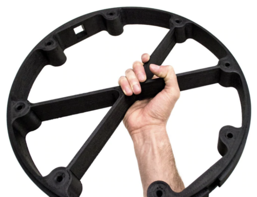
Around 6 hours later, the part is ready: it looks absolutely fantastic, fits perfectly, is very strong and it even weighs less!
How did we manage this? What settings did we use?
Lets walk through the process of how to decide what to do. We looked at the part & noticed the smallest sides were around 40mm long.
Given that, we decided we didn’t want that head to have to move any more than 40mm in 1 second. Thus, we decided the speed should be around 40mms (not 100mms).
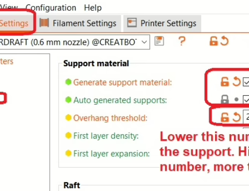
We looked at what kind of overhangs there were on the part. There were a few overhangs, but nothing unusual so we will need to use some supports but not too many because we will be able to pull those curves clean due to the slow speed. Given the comfortable surface, we decided to use 200 micron layers (not 100 micron).
By doubling the layer height (thickness of each layer) we have halved the number of layers you will need.
‘Hey, that is going to look really bad’ smirked one of the users, ‘We printed this at 100 micron & it still looks bad, 200 is going to be a waste of time..!’.
We then assessed the orientation of the part. It was going to need to be vertical. The part walls are prone to crack as thats where the clamps would pass.
However the middle section of the part was not going to have many forces and it was a larger surface area. This means we need to prioritise the strength in the walls.
The thinnest wall was 1.2mm and it had a 0.4mm outward feature protruding out. We decided to use 3 perimeters of 0.4mm walls to cater for this feature and to make the 1.2mm wall solid, as 3 perimeters would be perfect.
Since it was a tiny feature protruding out , a large 0.6mm nozzle was not going to be ideal.
The middle section no longer needs to be set to 100% infill, as the load thinnest load bearing walls already are.
We chose an infill of 30% as that was adequate enough to provide shell bonding to infill & supports for the top surfaces.
With infill down to 30% from 100%, the unnecessary waste of head time printing over the cosmetic areas was removed.
The 30% grid was mechanically strong enough to support the part shells & frame.
The total build time was brought down to around 6 hrs.
The user again thought ‘That is really silly, it’s going to take so long to make a part that’s going to look worse and be less strong than the part I made’.
6 hrs later, the part is ready. It looks superb. The clamp fit, no cracks, good strength. It’s light and even saved on material cost.
The inter layer adhesion of the part is superb, this meant the surface finish is good and the part is strong.
Time, Temperature, Throughput – get these right & you will get a perfect 3D print.
The user can’t believe this is possible ‘How can this even happen? Those numbers can not work!’.
No, the numbers were not off. The numbers were CHOSEN for this print with the part and the user’s needs in mind.
They wanted the part done in around 6 hrs, if we had more time we could do even better, but within the constraints, we used the correct set of combinations to still make a professional part.
So ladies & gentlemen, assess your parts, evaluate your 3D print’s goals, and then create your build.
This is not to say that inferior machines will still magically make good looking parts. Of course not.
But once you buy a good professional 3D Printer, keeping these tips in the back of your mind may help you make the best possible parts.
A lot of slicer’s claim to have AI now a days – what doesn’t. But don’t forget that the A in AI standards for ‘Artificial’.
The software is getting really good, but the first princples of physics & thermodynamics don’t change just becuase we have chat gpt available.
So do your own assessment quickly & you will appreciate the results.
I hope this post gave you an understanding of how we use professional grade 3D Printers over here correctly to get professional grade results. And you can do so too.
Thank you for reading.